Configuring a Show Technologies ShowIO “Digital Combo 8” OSC-Enabled Input/Output Box
I’ve been waiting for a long time for a simple Input-Output (IO) box that speaks the widely used OSC protocol, to allow things like sensors, operator controls, and small actuators and other devices to be easily interface with software like QLab. This year, one finally became available, and it’s affordable enough that I bought one to experiment with at home: The $200 Show Technologies ShowIO Digital Combo 8 Unit ($60 just for the raw board). The unit arrived right before I went out storm chasing, but I just finally found time to experiment with it over the last week.
Before proceeding, I should mention that this is a network interfacing box, so in order to configure and connect to it, you need to be comfortable with IP addresses, port numbers, network switches, and all that kind of stuff. I explain all that in my book Introduction to Show Networking. Also, I do talk a little basic electrical stuff that’s all low voltage; obviously, you are responsible for anything regarding electrical safety.
The Show Technologies SIO-S08DC unit I bought has four optically isolated inputs and four MOSFET (transistor) outputs, and runs on any power source from 12-24VDC. Being an old electrical guy, I started there. They have pretty straightforward wiring info here; here’s the relevant schematic representations, showing that the system is pretty flexible, easy to wire, and can connect to a wide variety of sensors and actuators.
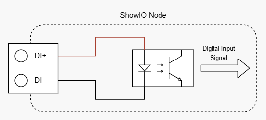
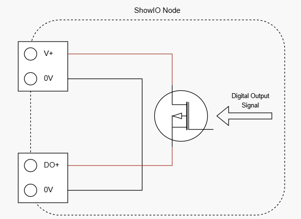
I got some little LED indicator lights and pushbuttons on Amazon. I already had a little 12VDC line voltage car power adapter with a “cigarette lighter” outlet, so I bought a plug and tail to feed that voltage to the ShowIO unit (for a real show application, I would likely use 24VDC). You can see all that wired up in the photo above. However, it’s worth noting here that they thoughtfully included little pushbuttons on the unit (see photo below); these allow you to test any input or output with the built in buttons and nothing connected. They also have LEDs on the unit indicating input and output state, which is a very useful tool for troubleshooting.
Here you can see output #2 turned on through OSC:
With the LEDs and pushbuttons, you can also test all your wiring before you do any configuration on the box at all.
Next up was connecting to the network. Out of the box, with all the DIP switches off, the default IP address is 10.11.12.10, and it receives on port 8888 and transmits on port 9999. Using the DIP switches, I changed the IP address to 192.168.10.83 (with 83 being the ASCII character for “S” for ShowIO).
After pinging the unit to verify the IP address, the first thing I did was use the excellent open source program Packet Sender to issue some basic configuration request commands to the unit to see if the connection was good, and I had all the port numbers right. You can see the commands in the top part of the screen capture below, and the return messages in the log at the bottom.
One of the things I’ve always hated about OSC is the required null padding octets. Every message has to contain a number of octets divisible by four, and has to end with a null octet (00 in hex). I always forget that even if a message is already divisible by four, you have to add four nulls (that’s the \00 \00 \00 \00 you see in the “Get OSC Info” message above); that wasted some time for me trying to remember that. Because I don’t have patience to deal with all the argument syntax and padding, and I own a QLab license, at this point, I just switched over to QLab, since it handles all that for me.
ShowIO Operation
One of the things that always takes time when controlling a new device is figuring out how the unit works at a low level. The device/system designers know this because they designed it, and are not always great at communicating it in their documentation; a new user (me) always starts with their own assumptions, and this can lead to confusion. After reading the OSC API documentation here (and emailing a couple times with the developers as I have with just almost every new device I’ve setup in the last 40 years except for one time), this unit works in a couple pretty straightforward ways.
Outputs
Outputs on many devices like this are very straightforward to control. The ShowIO receives on the configured IP address at port 8888 out of the box, so all you have to do is fire a command:
/sio/do/{channel}/set, where {channel} is a single character channel number followed by an argument of 1 or zero for on or off.
I didn’t want to mess with the OSC argument framing and null octet nonsense, so I just put these commands into an OSC message in QLab and let it handle it:
/sio/do/1/set 1
/sio/do/1/set 0
/sio/do/2/set 1
/sio/do/2/set 0
and so on, and it worked right away and is very responsive.
I have these commands written into cues in a test QLab workspace which you can download below.
Inputs
Inputs, conceptually, are a generally a bit more complicated to interface. There are generally two ways to get the status information from the input device: the interface unit either can be “polled”, or if the interface unit has enough processing power, it can generate and send messages to the controller whenever an input state transitions.
In polling, a controller device that wants the information sends a “What’s your status?” message over and over and over to the interface device, which then responds. If there’s no change, the interface just responds repeatedly, “off, off, off, off, off” (in some kind of response message that typically has to be parsed) and then if the input status changes (like someone presses a button) you’ll see a return like, “off, off, off, on, on, on, on, off, off” and so on. Some control software can handle this polling and represent all this to the (human) show control programmer with an internal variable, who can then program the system to take an action (run a cue or a sequence) based on the state change. This the traditional way that inputs have been processed in industrial control systems; the last time I programmed a system like this was in 2018 for the Gravesend Inn (RIP), where I built sensor input boxes based around Beckhoff network hardware (same kind of thing that theme parks often use) and polled them from Medialon Manager; details on all that here. Polling in general is the more complicated but reliable of the two approaches, because if there was “network traffic loss” or something, the system recovers the correct input status on the next poll. However, “network traffic loss” seems to be a scapegoat used to justify all kinds of problems; I’ve been doing control networks for about 30 years and have yet to experience impactful packet loss it in a well designed system. (In the old days, lots of problems would get incorrectly blamed on “MIDI Speed”, which was a real issue, but only if you were sending an entire orchestra’s worth of notes down a single old school MIDI line). I’m certainly not saying network packet loss can’t happen or shouldn’t be accounted for, but it should be very rare on modern, well designed network (and many problems can occur in the software rather than the network; I have stories for the bar). If I were using this interface box for something show critical, I would likely poll the interfaces just to account for that rare occurrence.
But for a simple test, I want to use this box with QLab, and it’s not straightforward to do this kind of polling (and parsing the return messages) in QLab (although I’m sure some better QLab programmers than me could figure it out). So for this test, I’m using the “interrupt-driven”approach, where, as I mentioned, when an input state changes (button or sensor is pressed/actuated or released/cleared), a message is sent to the controller. In closed, well designed networks, this approach can be very reliable.
Show IO Input Configuration
To tell the ShowIO box to send messages on input state change, we have to “subscribe” to an IP address and port number. The ShowIO will then send either a default message (which has to be parsed by the controller), or it can send a user programmed string (like an OSC command). That’s the approach I used, targeting a specific QLab workspace called “ShowIO-InputActions” and cues D1-D4. This way, you can just run a separate workspace on QLab that receives input from the ShowIO box, and use that workspace to fire cues inside QLab that do whatever you like. More on that later.
“Plain Text” OSC
Before going through the configuration file, I should talk a bit more about OSC and port numbers. Figure 53 was one of the first in our industry to select OSC as a control protocol for QLab. I’ve been doing low-level control stuff since the 1980s, and whined about having to deal with OSC null octets to fire QLab back in 2013 to the great people at Figure 53. Amazingly, they added a feature to listen to “plain text” OSC commands that are interpreted by QLab; if an incoming message looks like valid QLab OSC, QLab will process it and act on it (for a brief time, if I remember right, this was first implemented in version of QLab called “QLab-Huntington”). QLab of course can receive “full” OSC, and they do that on port 53000; for the plain text OSC-like messages, they listen to port 53535. The ShowIO can be configured to send whatever message and port number you want, but because I didn’t want to mess with debugging the null octets and the framing, for this, I’m just using the plain text pseudo OSC commands and the 53535 port (see next section).
QLab Configuration File and Configuration
Let’s go through the QLab workspace I made for configuration (you can download it below). To get started, I made a network patch for the ShowIO box. This patch is for my box at 192.168.10.83 and the default ShowIO port numbers; if you configured your box to different parameters, change this patch accordingly.
Here’s my configuration cues; I’ll demonstrate these in a video at the end as well.
I made these with a machine running a QLab “video” license; some of this may not work in the free version.
Note: Be careful with this workspace!
Q6 resets the device.
(Note that in testing I didn’t take my own advice and accidentally left this workspace open, and through pressing the button I have wired to the ShowIO, I went “Go” on the next cue, which was the reset cue, so it wiped the box.)
Q8 and 9 request the status information from the box; I just run wireshark to see the response, and I’ll show that in the video.
Q11-18 goes through each output and turns it on and then off using the commands I detailed above. You can copy these cues into your own workspace for control. These are also demo’d in the video.
Q20 tells the ShowIO box to “Subscribe” the IP address of the sending QLab machine at port 53535; after this, whenever an input state change takes place it will send the desired message. The syntax is:
/sio/cfg/osc/subscribers/subMe 53535
After sending this, I verified that the subscription was active by watching the response in Wireshark. I’ll demonstrate that in the video.
Q24-27 configure the ShowIO to send out a message whenever each of the inputs, DI1-4 goes “High”, or turns on. You can also, with a similar command, configure a message to be sent whenever the input goes “Low” or turns off. I didn’t do that for this simple test. The syntax for the first input is:
/sio/cfg/osc/reportMsg/di/1/hi/set "/workspace/ShowIO-InputActions/cue/DI1/start"
You then have TO REBOOT THE UNIT. I had to email the Show Technologies guy to figure this one out.
After that, in Q30 I just verify the state again.
September 4 2026 Update
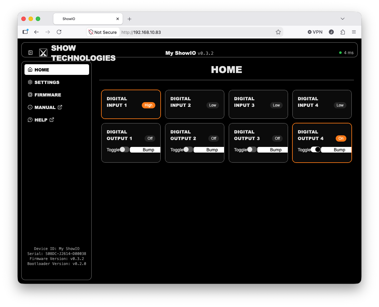
After I made this video, Show Technologies released an updated firmware version that added a very cool new feature, a web page served from the unit (using http:// not https://) that allows you to see the updated configuration and real time I/O status:
That should be it!
Dealing With ShowIO Inputs in QLab
You could just hardcode a message right into the ShowIO unit to fire whatever cue you like to take whatever actions you want. However, given that the nature of our business is change, I prefer a flexible structure.
So, the commands I programmed into the ShowIO box above reference a specific workspace titled “ShowIO-InputActions”; this is the pseudo-OSC message assigned to input 1 by the command in Cue 24 above:
/workspace/ShowIO-InputActions/cue/DI1/start
(Note: I developed and troubleshot all of those OSC messages in Packet Sender first and then cut and pasted those working strings into the QLab cues to program the ShowIO unit).
This means that whenever input one goes “high” (pushbutton on), it will send out this message to anything subscribed; in Cue 20 above, we added the Mac mini running QLab at 192.168.10.88 into the ShowIO’s subscription list.
In this ShowIO-InputActions workspace, I made four cues called DI1, DI2, DI3, and DI4. Using this workspace, you can change out my comment cues to trigger whatever you’d throughout the system as needed for your show, or leave them and auto-continue onto your action cues. For testing, I made a workspace that turns out the outputs and displays a graphic on the screen which you’ll see below and in the video.
QLab defaults to requiring a passcode to accept control messages over OSC, which is a good security practice. However, for my test, I didn’t really need that, so to keep things simple, I set up a QLab session to not require a passcode. On this screen I also ensured that the “pseudo” OSC Plain Text port 53535 was active.
Here’s the cues in this “ShowIO-InputActions” list:
Cue DI1 is, in this case, not really designed to be fired by the internal QLab Go button, but instead triggered by an external plain text OSC message from the ShowIO box.
DI1.1 auto-continues on, and displays a graphic on the screen.
DI1.2 auto-continues on, and fires back a “/sio/do/1/set 1” to the ShowIO box, to turn on output 1.
.50 seconds later, DI1.3 auto-continues, and turns off the output; DI1.4 then stops the graphic.
You can see all of this in the video.
Video Demonstration
Speaking of which, here’s the video! See if you can spot the hair from my cat Popsicle, who visited between shots.
Downloads
You can download a .zip file of the two QLab workspaces here.
In Conclusion
Getting any new interface device talking to a control system always seems to take me about a day, and this was no different. But with the configuration above, I’ve tested everything and done the “Huntington” test, which means (within reason, obviously) trying to “break” the system. I pressed all the buttons as fast as I could, pressed as many as I could at once, etc, and the whole system was solid. I should also mention that in addition to a show networking book, I have an Introduction to Show Control book as well, that goes through the principles and techniques I use when making show control systems.
Thanks to Shep and Trevor at Show-Technologies for making this cool box! I think it has many applications, and I know they are working on some stuff that should make all this configuration a bit easier. Let me know how they work out for you