Exploring Multicast in Entertainment and Show Networks
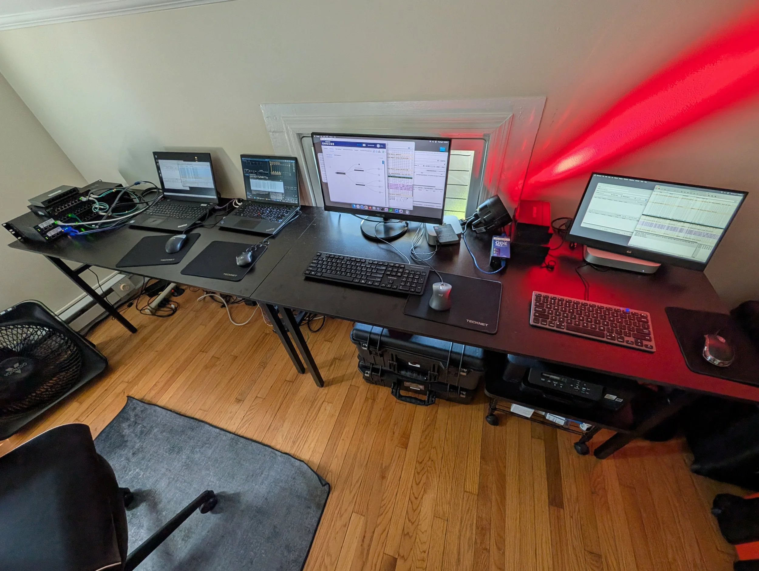
I’m starting to gear up for a future edition of my book, Introduction to Show Networking (no idea of a release date yet!), and I’m exploring topics that need a bit of expansion since the last edition. As show networks have gotten more complicated, issues with multicast data transmission have been increasingly arising; so, I’ve started with this topic. I learn things by doing, so I set up a bunch of the gear I use in teaching show networking workshops in my little lab space and spent some time going through everything. You can see my setup in the photo above.
From that initial exploration, I posted a video exploring multicast and IGMP snooping in a very intuitive way, and you might want to start there before going through all this low-level, abstract technical stuff. This post is a deeper dive into what’s happening with multicast inside the network. While exploring this low-level topic, I’m assuming here a fair bit of networking knowledge; this article really assumes that you’re comfortable with the material covered in Chapters 1-3 of the book (you can search inside the e-book here). This material will eventually go into the book; in the meantime, I’m going to share it here.
What is Multicast?
In Chapter 1 of the book I wrote, “When data is forwarded from one transmitter to two or more receivers simultaneously, this is called multicasting. Multicast communications on a network maximize efficiency by allowing the sender to send a particular packet of data only once, even though the data is delivered to multiple receivers.” Multicast is widely used in entertainment and show networks, because we have many situations where one device needs to send data to a bunch of others simultaneously: a lighting console telling 100 lights to fade up; a mixer sending an output signal to 20 speakers; or a video camera distributing signals to a dozen display units. Entertainment protocols that use multicast extensively include sACN for lighting, Audinate’s Dante for audio (AVB/Milan does efficiently send a single signal to multiple devices, but it runs at layer 2 only, so operates differently), and NDI for video. Multicast is kind of unusual because its functional operation is very closely coupled with the hardware of the network; the way the network is implemented will affect the way multicast operates. So, let’s start exploring through the model of different types of networks.
Multicast in Simple Unmanaged Switch Networks
The entertainment technology business operates in a sort of parallel world to the larger world of IT; we build big, complicated mission critical networks, but we often make networks without routers and that are disconnected from the internet. We have long used gear from outside our industry in ways that are pretty unusual (our closest relative in application is probably industrial control and automation), and in the early years of entertainment networking, we used hubs, which simply broadcast traffic to every interface. Full-duplex switches became affordable and took over our market; in the early days, most of those were unmanaged. Unmanaged, as we explored in Chapter 2, just means the switch is configured at the factory with no opportunity for the user to change things. Unmanaged switches, which continue to be in widespread use as of this writing, can work fine for simple systems (for example, a few devices connected to a single switch). However, I think it’s important to understand how things operate inside, and know the limitations; multicast is one of those things that can work or be problematic depending on the type of hardware that’s used, and how it’s configured.
To get started, here’s a little test setup I did where I have four machines connected via an inexpensive unmanaged switch (the same one I used in the video). Two of the machines are Windows PCs; two are MacOS. They are all set with the static layer 3 IP addresses 192.168.101.101 - 192.168.101.104, and everything has a /24 subnet mask (255.255.255.0). This switch, of course, is unmanaged and operates only at layer 2; so, it doesn’t get a management IP address.
(Note: Click any photo to enlarge.)
In general, when a piece of software wants to join a multicast group, it tells its parent Operating System (OS) like Windows, macOS, or Linux to do so. The OS then sends out a “Join” message. For this demo, I’m using an excellent open source piece of software called Packet Sender. On each of the four machines in Packet Sender, I entered a multicast group of 234.2.3.4 and clicked a button telling the machine to join that multicast group. (Note: the IP address range 224.0.0.0 to 239.255.255.255 is a special range of IPv4 addresses allocated for this purpose.)
Monitoring in Wireshark on the PC at 192.168.101.101 machine, I see this:
Packet Sender tells its MacOS or Windows (depending on which machine) to start listening and sending to this multicast address, and the OS sends out a “Join group 234.2.3.4…” message to the network using Internet Group Management Protocol (IGMP). (Note: Since IGMP sends these reports over IP without acknowledgement (like you’d find in TCP) many implementations send the message more than once, just in case a frame is dropped.) Those multicast management messages are sent by the host’s operating system to the special multicast address of 224.0.0.22, which is reserved for IGMP management. These multicast addresses are “link-local”, meaning they are only able to communicate on the local network segment and will not be forwarded by a router (without using a special protocol; more on that later). These are similar to the link-local or (aka APIPA/auto-IP) addresses we use commonly, like 169.254.x.x.
After these configuration steps, a single message sent from one of the four machines will be transmitted to all the others that have been told to listen to this multicast address. Here’s a screen shot from Packet Sender on the 101 machine. Take a look at the log on the bottom part of the screen. Can you figure out what’s happening?
From the PC at 101, I sent a message “Sending multicast from 101!” to the group at 234.2.3.4. Then the user (me) at each machine responded, “Got it on 102!” and so on. While we often talk about multicast as a tool to simplify transmission from one sender to many receivers, in reality, in many applications, it can be more like a group chat—any message sent to the group will be delivered to every host configured to listen.
In this small setup, it wouldn’t have been much work to send out three unicast messages to each of the three other machines, and not bother with multicast. However, imagine instead that we had to deliver audio to 500 networked speakers in an airport; the sender would have to maintain 500 point to point connections, which is a lot of work.
So now that we’ve talked a bit about multicast and these special layer 3 addresses, take a look at the diagram again, keeping in mind that earlier I said that this is an inexpensive unmanaged switch.
All the multicast messages we’ve looked at here have layer 3 IP destination addresses. At what layer do unmanaged, regular switches operate? Layer 2. So, this switch doesn’t know anything about layer 3 IP addresses. Remember from Chapter 2, layer 2 switches can do only three things with an incoming frame: forward to a particular interface, discard it, or flood (broadcast) it. One of the issues with unmanaged, inexpensive switches is that it’s not always clear how they have been factory configured; the majority I have seen are set to just flood multicast traffic. This means that these switches—designed to forward traffic onto to intended destinations—are basically operating with multicast in many ways like an old hub, just broadcasting all of it. In a little system, that might be just fine; However, as networks grow in complexity, it’s my opinion that it’s much better practice to manage the traffic.
Now that we have talked a bit about layer 2 and 3 addressing, here’s another screen shot from the 192.168.101.101 machine in this same setup, but with one slight change. Can you see the difference?
In this case, I changed the IP address of the fourth machine from 192.168.101.104 to 10.1.2.3. Here’s an updated diagram:
If you remember what we discussed in Chapter 3 about layer 3 subnets and subnet masks, you might be going “Hey, wait, there’s no router to connect networks, so how did that message go out to 10.1.2.3 and come back into 192.168.101.x logical subnet?” If you thought that, you’re definitely onto something; with this simple setup (four machines plugged into one unmanaged switch and no router), I’m not able to communicate between to the 10.1.2.3 machine from any of the 192.168.101.x machines with normal layer 3 unicast communications; if I ping between these machines, it fails.
But in this simple setup, because the switch doesn’t understand layer 3 traffic and sends the multicast frames to an internal layer 2 MAC address that gets broadcast, any device connected to this switch will receive all the multicast the traffic, regardless of the layer 3 address. When an OS on a connected host receives a frame from layer 2, it has to decide whether to accept that frame or ignore it. This is a routine part of network operations, and with the little bit of traffic I’m experimenting with here, the network and the hosts can easily handle it along with everything else they are doing. But what about streaming audio at 48kHz or 60fps video? Rejecting all that unneeded traffic is just work with no real benefit, and that could impact less powerful devices.
(Note:Of course, it’s generally not great practice to mix up machines on different subnets on the same switch (or VLAN) like this, but I did it here to make a point).
Now, to close out, I go to each machine and click a button in Packet Sender telling it to “Leave All Groups”. Packet Sender tells its operating system to stop listening to 234.2.3.4, and the OS issues “Leave” commands, which I can see on Wireshark running on the 101 machine:
And once again, even though it’s in a different logical layer 3 subnet, I can still see the multicast control traffic from the 10.1.2.3 machine, because it’s sent to the 224.0.0.22 multicast control address, which the switch then broadcasts.
So what if we want to explicitly manage the multicast traffic on network? The primary solution we see for this is IGMP Snooping. Let’s look at that by taking a look at our simple network, after changing the switch out to a managed model.
IGMP Snooping
Here’s the updated network, now connected to a show-grade Netgear AV M4250-8G2XF-PoE+ switch (Note: I’m using these switches in this demo because I bought them for my networking workshops and these are what I have available; other manufacturers implement this similarly.)
I’ve also added an ENTTEC ODE Mk3 unit, which receives the widely used sACN network lighting protocol, and outputs the low-level DMX lighting control standard; it’s also powered by the switch over PoE. The unit has two DMX outputs; one is configured to receive on sACN Universe 1 (and I have this DMX output connected to a little LED light in my setup which you can see in the video); the second output is mapped to sACN Universe 2. Additionally, I’m running ETC EOS software on the PC at 192.168.101.102 so that I can send sACN lighting control out to the ENTTEC box. (Note: If these low-level lighting control details don’t mean much to you, don’t worry because we’re here to look at multicast operations).
All the devices connected are in the same VLAN, with a Netgear AV lighting profile applied in the switch to all the interfaces manage the sACN traffic. (Note: Generally, I wouldn’t mix devices with different logical layer 3 addresses into the same VLAN as I have done in this setup, but again, I’m doing it here to demonstrate some concepts.)
Like the unmanaged switch in the previous demo, this professional, show-grade AV device also operates at layer 2, but many switches like this one include a feature that can be enabled called IGMP Snooping. This function “snoops” into the layer 3 multicast control traffic to know which layer 2 multicast traffic should be sent to which interfaces, and therefore to which devices. (Note: This switch also has pretty powerful layer 3 features like routing, but the low-level traffic forwarding operations still take place at layer 2.)
Here’s a screen shot showing the Multicast Groups table from the Netgear AV UI web interface on the switch after the network has been setup and running for a little while:
That’s a lot of confusing numbers, so let’s go through it. The first entry in the table is for interface (“forwarding port”) 2, which is connected to the PC at 192.168.101.102 and running the EOS software. The switch has snooped the control traffic, and determined that incoming traffic from multicast group 239.255.0.1 should be sent to this interface; additionally, outgoing traffic from the EOS PC should be forwarded to the other devices in the group at 239.255.0.1. (Note: Internally, at layer 2 the traffic will be forwarded to the allocated MAC address 01:00:5E:7F:00:01 that you can see on the right side of the table.)
Now, take a look at the third entry in the table. This interface connects to the ENTTEC DMX converter box, which has a management IP address of 192.168.68.10. This is just an address I use for my labs in my classes so I didn’t bother to change it, although in a real show application I would be much more systematic and intentional about all IP addresses in the network. In any case, this device also sent “join” messages and has been subscribed to the same 239.255.0.1 multicast group. So, any layer 2 traffic arriving from any other interface on this switch with a multicast destination address of 239.255.0.1 will be delivered to the ENTTEC box, which then converts it to DMX to control my little LED light. If you look up this IP address, you will find that 239.255.0.1 is the multicast IP address allocated in the ESTA sACN standard to DMX Universe 1.
So, what about the fourth entry in the table? Remember that the ENTTEC box has two DMX outputs, and the second one is subscribed to the second universe at 239.255.0.2. Right now, there’s nothing on this switch sending lighting control data into this multicast group, but that output has been configured and is just sitting and waiting in case that data arrives at some point. (Note: If you’re wondering, the box has some settings to handle prioritizing and/or merging traffic from multiple senders.)
Now look at the last two entries in the table, numbers 7 and 8 for 10.1.2.2 and 10.1.2.3. You’ll notice that those two are subscribed to multicast group 234.2.3.4; this is the group we were working with before. I told each of those machines, through Packet Sender, to subscribe to that multicast group, and traffic is sent back and forth between them. The switch snooped into this control traffic to add these to its table.
Now that we’ve gone through the table, why do you think there was no table entry for the 192.168.101.101 PC? It’s because I’m not running any software on it that is configured to connect to any multicast groups. (Note: If you’re curious about the second entry on the table from the EOS PC, search to find the protocol that uses the 224.0.1.35 IP address.)
While we’re talking about multicast groups in a switch, it’s a good time to point out that all switches have a limit on how many multicast groups they can handle. In things like sACN for lighting control, we tend to use more multicast groups than many consumer/business applications. Because of this, some switches can have multicast group limitations that are not even documented. There was a fantastic article about this by Mike Wood in ESTA’s Fall 2017 Protocol journal; additionally, there is software available to test multicast group capacity; I have those linked from the other post with the video, along with some other thoughts about types of switches.
Benefits of IGMP Snooping
Now that we’ve discussed how this works, we should remind ourselves why a switch manufacturer would go to all the trouble to implement this (and, more importantly, why you should care about this). In terms of enhancing and managing network performance, IGMP snooping is a powerful tool, because when it’s configured properly, multicast traffic will only be delivered to physical interfaces connected to devices that have told the system they want to receive that traffic. To see this in action, here’s a Wireshark traffic capture on machine 192.168.101.101, showing an initial ARP transaction and then a ping from 101 to 102. Remember that this 101 machine is connected to the same switch and in the same 101 VLAN as all the other devices in the network.
While this ping was running, I changed the levels of lighting channels on the EOS PC, sending multicast streaming ACN traffic to the ENTTEC box on 239.255.0.1, and I also had the two 10.1.2.x machines exchange messages over the 234.2.3.4 multicast group. But unlike with the unmanaged switch, none of this traffic was ever delivered to the 101 machine, because the switch did not see any multicast “join” messages for these groups from the 101 machine. Again, with low bandwidth traffic like this, this isn’t really a big problem. But imagine if I was multicasting uncompressed video between three other devices on the same switch, but had IGMP Snooping disabled (meaning all multicast frames would be broadcast)? A modern, show grade switch could probably easily handle it, but could all the other, non-video receiving devices handle that deluge of unneeded traffic, especially without a noticeable delay? Maybe, but why make them do all that extra work?
I demonstrate this in the video; if you didn’t watch it before, now would probably be a good time.
IGMP Querier
The software service that handles all of this multicast traffic management is called the IGMP Querier. Any multicast traffic on a switch/VLAN is forwarded to the querier, which then forwards it out to the appropriate (joined) interfaces based on the Multicast Forwarding Data Base (MFDB), a table that looks similar to the simplified version we looked at above. In this small system, with only one switch and one VLAN, no DHCP and no routing enabled, the automatically configured querier (which just exists somewhere internally in the switch software) works fine:
To keep its multicast table current, the querier also periodically sends out requests to see if the receiving devices still want to receive traffic; this is especially useful if devices are being connected to and disconnected from the network. I made this Wireshark capture on the 10.1.2.3 machine and marked the “Membership Query, general” messages (in black):
These have a source link-local address of 169.254.100.100. How can we verify where these are coming from? Let’s look at the layer 2 address in one Membership Query frame in the Wireshark capture:
You can see that it comes from a Netgear device, and referring back to the diagram, there’s only one Netgear device in this system. To prove this for myself (remember my learn by doing thought from above), I went and reconfigured the querier address to 10.1.2.1:
And you can see it update in Wireshark at 10:47:16:
The interval that these updates are issued seems to vary by manufacturer; on this Netgear AV switch with a “Lighting” profile applied, it sends out these Query message about every 60 seconds.
And one really important note with all this: it’s really important that only one querier is operational in each VLAN (or switch if you’re only using one switch and one VLAN). Speaking of queriers and VLANs, so far, we’ve looked at a simple setup with one VLAN. Let’s see what happens if we split out the devices into two VLANs, one for lighting control, and the other for audio.
IGMP Snooping and Multiple VLANs
I reconfigured the network, keeping the two PCs and the ENTTEC DMX box in the 101 Lighting VLAN, and moved the two Macs into an Audio VLAN 201. Here’s a screen shot from the AV UI of the switch:
VLANs segment traffic at Layer 2; so, there are now two separate multicast snooping operations, but both VLANs show up in the multicast table:
Notice that we see the same multicast groups of 239.255.0.1 and 234.2.3.4, but notice the changes in the left VLAN column. (Note: I realized after I had taken this entire setup apart that I somehow missed the interface 2 EOS subscription to 239.255.0.1; I figured I’d mention it here rather than rebuilding and reconfiguring the entire system to update a screen shot.)
Below is a Wireshark capture from the 10.1.2.3 machine on the 201 VLAN. Notice that even though we can see in the table above that other machines in the other 101 VLAN at 192.168.101.x are managing multicast, we don’t see any of that traffic because the VLANs are segmenting the traffic out at layer 2.
And why is the querier IP address different from the 10.1.2.1 that I set above? Remember that each VLAN has its own querier. Speaking of VLANs, through trunking, VLANs can also span multiple switches in larger setups. What happens to IGMP snooping and the querier then?
IGMP Queriers in Networks with Multiple Switches
As I mentioned previously, it’s important that there’s only one querier operating in any VLAN. How this is configured and handled varies by manufacturer, but I’m going to talk here about Netgear AV stuff because that’s what I own. I setup three switches into a “hub and spoke” topology, taking the one smaller AV M4250-8G2XF-PoE+ switch from the previous setup, using it as a “core”, and connecting via SFP and fiber to two other, slightly larger AV M4250-10G2XF-PoE+ “access” switches. Here’s what the topology looks like in Engage, the software Netgear AV provides for managing systems with multiple switches (Note: I generally just use the web UI and the “Out Of Band” connection port since it’s much more straightforward, but Engage makes managing multiple, connected switches much easier).
The switch at the left is designated in Engage as the core switch, with fiber trunk connections to the two other access switches. This is what it looks like in real life:
(Note: I’m just using short fiber jumpers, but of course the advantage of fiber is that those switches could be spread out over a large distance.)
I set interfaces 1-4 (on the left) on all three switches to the lighting VLAN 101; I set 5-7 on the core switch and 5-8 on the access switches to the audio VLAN 201. I left interface 8 on the core switch for management, and this is how I connected Engage; that cable is disconnected in this photo so you can see the fiber connections better.
Here’s what the VLAN assignment process for the lighting VLAN looks like in Engage:
In Netgear (and most switches I’ve seen) the active IGMP querier is elected by having the lowest IP address. So, for lighting VLAN 101, I set the lowest querier IP address to live on the core switch. Multicast traffic has to be forwarded to the querier for processing, so it makes sense in this case for the querier to live on the core switch since, well, it’s at the core (look again at the topology if that’s confusing).
(Note: this isn’t the most consistent IP address scheme, but you get the idea. I have a lot of this stuff pre-configured for my class labs and didn’t want to go back and change it all; in a real show application, of course I would.)
You can see on the right that the “Operational Status” is correct at the core switch (management IP address of 192.168.101.21, querier address of 192.168.101.1). One of the things they emphasize in the Level 3 Netgear Certification Training is to make your decisions and operations very “intentional”; this is the kind of thing they are talking about. This little system certainly would have worked fine with (a single) querier operating on any switch, but it’s much better to think about your traffic flow and select the best option. Let’s say that with this same network topology, I had a lighting console and a primary DMX gateway physically sitting next to each other and connected to the second 192.168.101.12 access switch. In that case, it would make more sense to designate that 192.168.101.12 switch to operate the querier, since there would be so much multicast traffic between the console and the gateway. There’s no need to send all that traffic to the core switch and back. Could this high performance gear handle it? Most likely. But why push it? Also, in our “show must go on” business, we have to think of handling failures. What if someone ran over the fiber run from the core to the .12 access switch? If I had the querier set there, lighting, at least, would be able to continue to operate in some fashion.
For similar reasons here, note too that I set the core switch with the lowest IP so it would win the election; but I left the others set to participate. This way, if the fiber got cut as mentioned above, the access switch, after some time, would elect its local querier, and it would eventually take at least multicast traffic within that access switch. I talk more about these ideas of redundancy and failure tolerance in Chapter 4 with my list of suggested best practices, and Chapter 5 when I go over my system design principles.
With all that in mind, let’s take a look at a Wireshark capture showing some of the IGMP messages captured from the PC running EOS at 192.168.101.101.
You can see the “Membership Query” messages sent out from the querier on the core switch at the address that I set at 192.168.101.1, and responses from 192.168.101.102, which is the PC running EOS and connected by the white cable to interface 1 on the far left of the top access switch in the picture. You also see responses from the PC at 192.168.101.101, which is connected to interface 2 in the bottom switch in the picture and connected with the purple cable. On this 192.168.101.101 machine, I started up an open source software called sACNview; it listens to many sACN streams and on startup it subscribes to many multicast groups in the sACN range (239.255.0.x). So, all of this shows that the querier is able to manage traffic across a VLAN spread across three separate switches and connected through the fiber trunks. This is the kind of verification that I think is really good practice to do routinely when building a system. I suck at numbers and can’t tell you how many times I’ve mistyped an address or subnet mask or something; with something misconfigured, the system seems to be working, but may not be working in the way I intended.
In that vein, think about what’s missing from this capture (and should be)? Any multicast control traffic from the 201 audio VLAN, even though there is multicast activity on 234.2.3.4 group passing through all three switches. This is how it’s intended to operate, since the 234.2.3.4 traffic is in a separate VLAN and managed by its own querier.
In this iteration of the network, keeping lighting and sound traffic segmented was a design goal, because the lighting and sound systems don’t need to talk to each other (if they did I’d set up routing in the switch), and operate on completely different protocols. Obviously, all of this puts some load on the switch hardware and software, but these are powerful switches designed for much heavier traffic load than I have here.
Multicast Routing
Speaking of heavy traffic load, imagine a situation where we had video senders in one VLAN spread across several switches, and video receivers in a different VLAN on the same switch, along with a fiber connection to another switch in overflow space somewhere else in the building? It’s good for operational reasons to keep that all this traffic segmented by space and function (and not “flat” as the network people call it), but we need to send multicast from one VLAN to another. For that, you can use the Protocol Independent Multicast (PIM) protocol. To demonstrate that, though, I’d have to do another setup, and I think I’ve likely already saturated your brain enough for one article.
Conclusion
I hope this has helped you understand multicast a bit in entertainment and show networking applications. Multicasting is a big part of show networks these days; with an understanding of how switches manage it, you can decide how you’d like to manage it (or not). I have more on all this the “Benefits and Disadvantages of Various Switch Types For Show Networks” section on this link along with the video demonstration I mentioned.
Also, as I said, I think many show people, like me, learn best by doing; you can do a lot of what I did here with some cheap or old computers and some inexpensive switches and open source software. And finally, if you want a hands-on introduction to the fundamentals, I teach two-day hands on workshops; one of the rare public ones is coming up later this month in Baltimore and there’s still, as of this writing, a few seats are available!